The CAD Submittal Standards are shown on the Home page of the portal. This portion of the Help documentation is intended to provide additional discussion and guidance for meeting those standards. The 8 standards include:
The portal will accept drawing (DWG) file formats with a .dwg file extension (versions 14-18). The DWG format is the native file format for Autodesk's AutoCAD software and specifications are available here: https://www.autodesk.com/products/dwg. If another file type is required to be included in the engineering and design of utility assets, please coordinate directly with the Utility Services Department.
In addition, for the portal to recognize the submittal file, the DWG file must be named with an underscore and the letters "UT" for utilities at the end of the file name and before the dot file extension ("_UT.dwg"). The following naming convention is recommended: "ANYPROJECTNAME_UT.dwg".
On the web submittal form, check the box at the bottom confirming that the electronic drawing submittal matches the approved mylar submitted to the Development Services Center.
In order to accommodate the assimilation of utility data across the City, a single coordinate system is adopted as the standard. The CAD file must be defined in the NAD83 State Plane Nevada East Survey Feet (FIPS 2701; WKID 3421; EPSG 3421) coordinate system. The Utility Submittal portal will perform two checks to see if the CAD file submitted is moved to the coordinate system. The first check will verify whether or not the CAD file has been defined with the expected coordinate system using the Assign Coordinate System tool within the CAD software. The second check will verify if the coordinates of the data within the CAD file fall within the City boundary. It is important to note that the file coordinate system definition and the geo-location of the data are separate settings which should be addressed independently. If the data is not properly geo-located the submittal will fail without further reporting.
The CAD data must be stored using simple points, lines and closed polylines (polygons). Due to various approaches to design standards, the data is simplified to center or centerline representations for storing locations in the City's asset database.
Each drawing layer in the CAD file may only store a single data type. For example, if a layer is created to store proposed water valves, only simple points representing the center of water valves may be stored in that layer. Extraneous information such as text blocks, annotation, leader lines, etc. may not be stored in that data layer.
CAD data stored in the CAD layers must be contiguous and coincident where appropriate. For example, a sewer main pipe will be drawn using a line that extends to and whose endpoint is coincident with the end of the adjoining sewer main pipe. The coincident endpoints will also be coincident with the point representing the center of the sewer manhole located between the two sewer main pipes.
The CAD Validator will read the insertion point of the submitted objects during conversion to check for coincidence.
Layer naming ensures the appropriate attributes are applied to the correct layers during validation. There are three components to proper layer naming: Status, Utility Type and Layer Name.
Each layer in the CAD file should contain a prefix that defines how the drawing is processed. Layers with the prefix “EX_" represent features/objects that will be considered existing infrastructure or infrastructure not added per the mylar(s) associated with this submittal. Existing infrastructure should be present in the CAD file delivered through the Records Request. Layers with the prefix "DM_” represent existing features/objects that are identified for demolition with this submittal. Only layers with the prefix "PR_" (Proposed) will be validated through the CAD Submittal Portal as new infrastructure. Layers with the prefix EX or DM will only appear as Unmatched Layers in the Details report for the submittal, available on the My Uploads page.
The letter after the status indicates the type of data the layer will store: water, reclaim water or sewer infrastructure. These data types are represented by “W_”, “R_” or “S_”, respectively.
The layer name will follow to indicate what type of data is stored in the layer, for example, MAIN for main pipes, or LATERAL for lateral pipes. A properly formed layer name for proposed sewer mains would be PR_S_MAIN.
There are 3 methods (file types) available in which to submit attributes attached to the data through the portal.
Attributes may be included in:
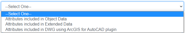
Each of these methods/file types have specific requirements. For validation purposes, only one type of attribution may be used per CAD file with the exception of using blocks with point layers (see Block Attributes).
Attributes Included in Object Data
Object data tables are available using AutoCAD Map 3D or Civil 3D. Object data tables apply to all AutoCAD object types (points, blocks, lines, polygons).
When selecting the Object Data file type please provide one CAD file (DWG) with object data tables embedded within the file. No additional files are required when submitting a file with object data. A template CAD file with any existing utility data and pre-defined object data tables is available through the Records Requests process. Attach data tables to each object to enter attributes and complete the attribution.
Attributes Included in Civil 3D Extended Data
When selecting the CAD File Type for Civil 3D Extended Data, be sure to embed the attributes within the DWG file. No additional files are required when submitting a file with extended data. Civil 3D Extended Data is typically hidden from the AutoCAD user and can be very challenging to modify without a custom application.
Attributes Included with ArcGIS for AutoCAD Plugin
With the ArcGIS for AutoCAD plugin, the attributes are stored directly in the CAD DWG file and may be populated from an ArcGIS tab within AutoCAD after the plugin is installed. This method for storing attributes has some advantages. First, when populating attribute values, a drop-down list will appear and only allow acceptable values following the layer attribute table in the CAD Standards. Second, multiple CAD entities from the same layer can be selected for attribute value population at the same time. Note that the attribute tables from the CAD Standards will only appear in the specific DWG file provided by the City through the Records Request process. For more information on this method, please coordinate directly with Utility Services.
One CAD file (DWG) is required with Plugin data embedded within the DWG file for this CAD File Type. No additional files are required when submitting a file with ArcGIS Plugin data.
The plugin is free and available for AutoCAD, AutoCAD Map 3D, and AutoCAD Civil 3D versions 2013 or later, both 32 bit or 64 bit versions of the software. More information on using the plugin can be found at the following website:
https://www.esri.com/en-us/arcgis/products/arcgis-for-autocad